Engineer Innovation Podcast
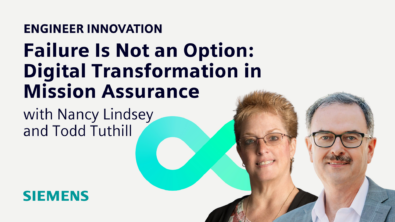
Failure Is Not an Option: Digital Transformation in Mission Assurance
May 01, 2024
In this episode, listeners are treated to a profound discussion on aerospace innovation and digital transformation with Nancy Lindsey, a NASA technical expert in reliability, maintainability, and availability, and Todd Tuthill, Vice President for the aerospace, defense and marine industry at Siemens Digital Industries Software.