Tecnomatix
Maximizing efficiency: Integrating layout planning into battery production
April 25, 2024
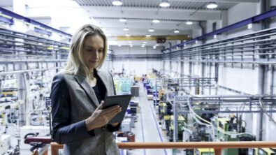
Battery Production: In her lecture titled "Enhancing Battery Production: Integrating Layout Planning into Material Flow Simulation," Louisa Christin, Project Manager in Production Planning at EBZ Ravensburg GmbH, outlined the synergistic benefits of integrating layout planning and material flow simulation in the context of battery production. By drawing from three compelling use cases, Louisa showcased the evolution of battery production in material flow simulation, emphasizing the challenges encountered and the strategies employed to overcome them. Benefits of the integration, including increased throughput, optimized resource utilization, and streamlined processes are shown. Louisa's presentation provided a overview of how EBZ is optimizing battery production through the power of Plant Simulation.